GIP receives patent protection in the USA for virtualization of power grids
The US patent office has granted the extension of the scope of protection of the GIP US patent US 10,361,564 B2: now not only the packet-based CrossBar, called QBar, as a dedicated network node is protected, but also the execution of this as a virtual or logical QBar for the distribution of electrical power is included in the scope of protection.
With this technology, it is now possible to virtualize and highly dynamically segment power networks. In particular, this technology allows virtual overlay networks to be realized for packet-based power transmission on standard power networks. This then makes it possible to build a quantum grid based on standard power grids that is divided into cells. These cells can exchange power with each other on a packet basis using the virtual QBar. A particular advantage of this cell-based Quantum Grid is the firewall function, which prevents a large-scale spread of a blackout and at the same time offers the possibility of operating individual cells in island mode and then interconnecting them again to form an overall grid without the usual problems of "black start".
This invention relates to a method of transmitting power in an electrical power system, in which the power grid includes a controllable crossbar network.
In a first embodiment, US 10,361,564 B2, this crossbar network is implemented as a dedicated, localized controllable crossbar network operated by the method according to the invention. This embodiment is referred as a QBar.
As an extension to the first embodiment, the scope of protection has now been enlarged to include the second embodiment. The second embodiment, the controllable crossbar network is implemented in a distributed manner via a higher-level power grid. This embodiment is referred to by as a virtual QBar.
The controllable crossbar network, which is shown in Fig. 4, has several ports to which distinguished nodes, that are sources or loads in the transmission of electrical power, are connected.
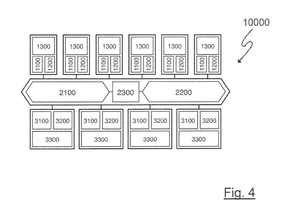
In this case, storages, which can be both source and load, are always considered either as source or load according to the mode of operation. These distinguished nodes transmit data about their states to a control entity. Each of the terminals comprises a power controller.
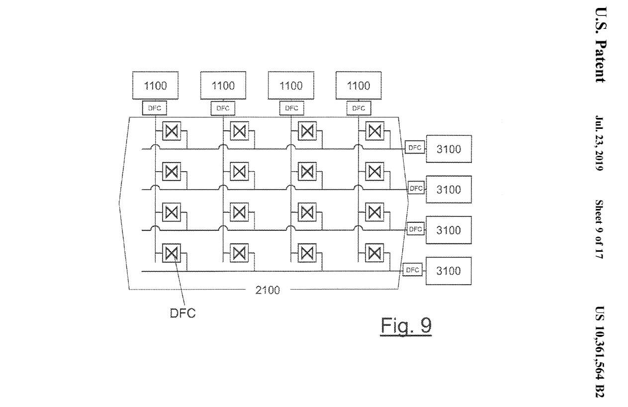
The lines interconnecting the terminals are in turn interconnected by power controllers. By the control of those power controllers according to the invention, that interconnect the connecting lines to the terminals, a matrix circuit Fig 9 for the directly connected distinguished sources and loads is implemented. For details, please see the patent.
In such a crossbar network, all sources and loads connected to this crossbar network are electrically interconnected. At least one load can be connected to a plurality of sources or at least one source can be connected to a plurality of loads. It is realized according to the invention that an electric current can flow from any one of the plurality of connections of the subnetwork to any other one of the plurality of connections of the crossbar network.
In the first embodiment, only the distinguished sources and loads are directly connected to the connections of the crossbar network and interconnected via the power distributor.
In the second embodiment in the case of distributed implementation within a higher-level power grid, the crossbar network is formed by lines of the higher-level power grid and power controllers as connections of the crossbar network. The lines of the higher-level power grid are connected to each other via power controllers within the section of the grid that implements the crossbar network.
The terminals are interconnected by appropriate control of all power controllers. The lines of the higher-level power network are connected to the terminals, which are located outside the distributed implemented crossbar network, then form sources and loads of the subnetwork in the same way as the distinguished sources and loads directly connected to the subnetwork via its terminals.
The crossbar network implemented in this distributed manner is characterized by the fact that the transmission of power between the designated sources and loads directly connected to the subnetwork takes place independently of the control and balancing of the power transmission in the overall higher-level network. The distinguished sources and loads directly connected to the crossbar network are not part of the balancing of the overall higher-level network.
The power controllers at the terminals are set up in such a way that the electric current flowing via the respective terminal can be adjusted according to its power P(t) as a function of time t. The designated nodes communicate with a control device and the control device communicates with the power controllers such that the power controllers receive data from the designated nodes during operation.
The method comprises controlling a distribution of a current flow with the electric power P(t) as a function of time t, according to the power P(t) required and provided at the terminals. The controller is connected to each of the power controllers and arranged to calculate for each of the terminals, at a freely selectable time interval, the electrical power P(t) to be transmitted as a function of the data received from the distinguished sources or loads.
The control system is further set up so that for each point in time within the time interval, the actual electrical power transmitted via the respective connection is controlled by actuating the respective power controller so that the actual electrical power is equal to the previously calculated electrical power P(t).
For example, a state of the crossbar network can be realized in the following way. By calculation, a set of n sources Qi of the crossbar network is chosen which can transmitted for each time t in a time interval T the power P(t). The related power controllers in the crossbar network connecting these sources with the demanding load are controlled such that $$\sum P_i(t) = P(t)$$ for $$\forall t\in T$$ is fulfilled. Where P(t) is the calculated power demand of these load for each $$t \in T$$
The calculation of the electrical power as a function of time P(t) (e.g. for terminals to which electrical storage units are connected as a load), is carried out by measuring the state of charge of the storage unit and using a mathematical battery model. This battery model calculates the capacity for the future output, as well as the input, of electrical power P(t) via the respective terminal. The calculation for the power demand of a load can be done, for example, by forecasting. Similarly, the calculation for regenerative sources is also done by prediction, e.g. using AI.